MCXE31B SMR (Secure Memory Region) Example#
This example demonstrates how to configure and use Secure Memory Regions (SMR) on MCXE31B devices. SMR provides runtime verification of application code integrity using cryptographic authentication.
What is SMR?#
A secure memory region (SMR) is defined by a start address and a size, associated with a proof of authenticity, either a MAC or an RSA/ECC signature, which authenticates the region’s content.
The host can define up to 8 SMR clustered into the SMR table. It must also provide the proof of authenticity for each memory region content.
For all SMR that have been defined, the HSE verifies the authenticity of memory contents:
During the device start-up phase (after reset)
While the application(s) is(are) running on the host side (during run-time)
The SMR verification results translate into sanctions imposed on the system by the HSE:
Unsuccessful verification can keep select subsystems on the host side in reset state; those subsystems are referenced in the Core Reset (CR) table
Likewise, failing to verify certain SMR can render selected keys within the HSE unusable; these restrictions are defined individually for each key via the SMR verification map
Example Overview#
This notebook demonstrates:
Key catalog configuration and key provisioning
SMR entry configuration and installation
Core Reset (CR) entry configuration
Authentication tag generation
1. Prerequisites#
SPSDK installed with examples extension:
pip install spsdk[examples](Please refer to the installation documentation.)MCXE31B Freedom board
HSE firmware must be installed on the device
J-Link debugger connected
UART connection established (COM port configured)
import os

from spsdk.utils.jupyter_utils import YamlDiffWidget

# This env variable sets colored logger output to STDOUT
%env JUPYTER_SPSDK=1
# Set a magic for command execution and echo
%alias execute echo %l && %l
%alias_magic ! execute
env: JUPYTER_SPSDK=1
Created `%!` as an alias for `%execute`.
# Configuration
WORKSPACE = "workspace/"
INPUTS = "inputs/"
KEYS = "keys/"
VERBOSITY = ""

# Communication parameters
BLHOST_CONNECT = "-p COM26"  # Change this to your actual COM port
FAMILY = "mcxe31b"

# Key catalog and key info files
KEY_CATALOG_CONFIG = INPUTS + "key_catalog.yaml"
KEY_INFO_CONFIG = INPUTS + "key_info_ecc.yaml"
KEY_INFO_BIN = WORKSPACE + "key_info_ecc.bin"

# Key files
PRIVATE_KEY = KEYS + "ecc256.pem"
PUBLIC_KEY = KEYS + "ecc256_pub.pem"

# SMR and CR configuration
SMR_ENTRY_CONFIG = INPUTS + "smr_entry.yaml"
CR_ENTRY_CONFIG = INPUTS + "cr_entry.yaml"
MBI_SMR_CONFIG = INPUTS + "mbi_smr.yaml"

# Application binaries
MBI_CONFIG = INPUTS + "mcxe31_mbi_smr_config.yaml"
MBI_OUTPUT = WORKSPACE + "mcxe31_mbi_smr.bin"

# Output files
AUTH_TAG_SMR = WORKSPACE + "auth_tag_smr.bin"

# Create workspace directory
os.makedirs(WORKSPACE, exist_ok=True)
2. Initialize Flashloader#
Before we can communicate with the device, we need to initialize the flashloader using J-Link.
# Initialize flashloader using J-Link
# Make sure J-Link is connected to the board and the board is powered on
%! "JLink.exe" -NoGui 1 -ExitOnError 1 -CommandFile "inputs/init_flashloader_cmd.jlink"
"JLink.exe" -NoGui 1 -ExitOnError 1 -CommandFile "inputs/init_flashloader_cmd.jlink"
SEGGER J-Link Commander V8.44 (Compiled Jun 18 2025 12:17:39)
DLL version V8.44, compiled Jun 18 2025 12:16:46

J-Link Commander will now exit on Error

J-Link Command File read successfully.
Processing script file...
J-Link>device S32K314
J-Link connection not established yet but required for command.
Connecting to J-Link via USB...O.K.
Firmware: J-Link V9 compiled May  7 2021 16:26:12
Hardware version: V9.20
J-Link uptime (since boot): N/A (Not supported by this model)
S/N: 59201842
License(s): GDB
VTref=3.324V
J-Link>si SWD
Selecting SWD as current target interface.
J-Link>speed 4000
Selecting 4000 kHz as target interface speed
J-Link>connect
Device "S32K314" selected.


Connecting to target via SWD
ConfigTargetSettings() start
ConfigTargetSettings() end - Took 26us
InitTarget() start
SDA_AP detected
Unlocking device if necessary...
  Device is not locked. Proceeding without the unlock procedure.
Checking if debug access is already enabled...
  Core already enabled
Checking if HSE firmware is installed...
  HSE firmware not installed
Checking if Cortex-M7_0 and Cortex-M7_1 are operating in lockstep mode
  Lock step mode disabled or not available
InitTarget() end - Took 5.37ms
Found SW-DP with ID 0x6BA02477
DPIDR: 0x6BA02477
CoreSight SoC-400 or earlier
AP map detection skipped. Manually configured AP map found.
AP[0]: MEM-AP (IDR: Not set, ADDR: 0x00000000)
AP[1]: APB-AP (IDR: Not set, ADDR: 0x00000000)
AP[2]: MEM-AP (IDR: Not set, ADDR: 0x00000000)
AP[3]: AHB-AP (IDR: Not set, ADDR: 0x00000000)
AP[4]: AHB-AP (IDR: Not set, ADDR: 0x00000000)
AP[5]: AHB-AP (IDR: Not set, ADDR: 0x00000000)
AP[6]: MEM-AP (IDR: Not set, ADDR: 0x00000000)
AP[7]: MEM-AP (IDR: Not set, ADDR: 0x00000000)
AP[4]: Skipped ROMBASE read. CoreBaseAddr manually set by user
AP[4]: Core found
CPUID register: 0x411FC272. Implementer code: 0x41 (ARM)
Cache: L1 I/D-cache present
Found Cortex-M7 r1p2, Little endian.
FPUnit: 8 code (BP) slots and 0 literal slots
ROM table scan skipped. CoreBaseAddr manually set by user: 0x40250400
I-Cache L1: 8 KB, 128 Sets, 32 Bytes/Line, 2-Way
D-Cache L1: 8 KB, 64 Sets, 32 Bytes/Line, 4-Way
SetupTarget() start
Initializing ECC RAM...
  RAMCodeAddr: 0x20000000
  RAMInitAddr: 0x20000010
  RAMInitSize: 0x00007FF0
  InitPattern: 0xDEADBEEF
  ECC RAM initialized successfully
Initializing ECC RAM...
  RAMCodeAddr: 0x20000000
  RAMInitAddr: 0x20400000
  RAMInitSize: 0x00004000
  InitPattern: 0xDEADBEEF
  ECC RAM initialized successfully
SetupTarget() end - Took 19.3ms
Memory zones:
  Zone: "Default" Description: Default access mode
Cortex-M7 identified.
J-Link>reset
Reset delay: 0 ms
ResetTarget() start
-- Identifying target device...
-- SWD selected. Executing JTAG -> SWD switching sequence...
SDA_AP detected
Checking if core is already enabled...
  Core is not enabled yet. Performing enable core sequence...
  Core enabled
Unlocking device if necessary...
  Device is not locked. Proceeding without the unlock procedure.
ResetTarget() end - Took 413ms
Device specific reset executed.
J-Link>halt
PC = 0040411C, CycleCnt = 00000000
R0 = 00000000, R1 = 00000000, R2 = 00000000, R3 = 00000000
R4 = 00000000, R5 = 00000000, R6 = 00000000, R7 = 00000000
R8 = 00000000, R9 = 00000000, R10= 00000000, R11= 00000000
R12= 00000000
SP(R13)= 20404000, MSP= 20404000, PSP= 00000000, R14(LR) = FFFFFFFF
XPSR = 01000000: APSR = nzcvq, EPSR = 01000000, IPSR = 000 (NoException)
CFBP = 00000000, CONTROL = 00, FAULTMASK = 00, BASEPRI = 00, PRIMASK = 00

FPS0 = 00000000, FPS1 = 00000000, FPS2 = 00000000, FPS3 = 00000000
FPS4 = 00000000, FPS5 = 00000000, FPS6 = 00000000, FPS7 = 00000000
FPS8 = 00000000, FPS9 = 00000000, FPS10= 00000000, FPS11= 00000000
FPS12= 00000000, FPS13= 00000000, FPS14= 00000000, FPS15= FFFFFFFF
FPS16= 00000000, FPS17= 00000000, FPS18= 00000000, FPS19= 00000000
FPS20= 00000000, FPS21= 00000000, FPS22= 00000000, FPS23= 00000000
FPS24= 00000000, FPS25= 00000000, FPS26= 00000000, FPS27= 00000000
FPS28= 00000000, FPS29= 00000000, FPS30= 00000000, FPS31= FFFFFFFF
FPSCR= 00000000
J-Link>loadfile ./inputs/flashloader_loader.elf
'loadfile': Performing implicit reset & halt of MCU.
ResetTarget() start
-- Identifying target device...
-- SWD selected. Executing JTAG -> SWD switching sequence...
SDA_AP detected
Checking if core is already enabled...
  Core is not enabled yet. Performing enable core sequence...
  Core enabled
Unlocking device if necessary...
  Device is not locked. Proceeding without the unlock procedure.
ResetTarget() end - Took 410ms
Device specific reset executed.
Downloading file [./inputs/flashloader_loader.elf]...
Comparing flash   [000%000%050%050%100%] Done.
J-Link: Flash download: Bank 0 @ 0x00400000: Skipped. Contents already match
O.K.
J-Link>loadfile ./inputs/flashloader.elf
'loadfile': Performing implicit reset & halt of MCU.
ResetTarget() start
-- Identifying target device...
-- SWD selected. Executing JTAG -> SWD switching sequence...
SDA_AP detected
Checking if core is already enabled...
  Core is not enabled yet. Performing enable core sequence...
  Core enabled
Unlocking device if necessary...
  Device is not locked. Proceeding without the unlock procedure.
ResetTarget() end - Took 412ms
Device specific reset executed.
Downloading file [./inputs/flashloader.elf]...
O.K.
J-Link>go
Memory map 'after startup completion point' is active
J-Link>exit

Script processing completed.
3. Install HSE Firmware#
All MCXE31 devices are delivered from factory without security firmware, as a measure to ensure a chain of trust and guarantee that only authorized parties get the security firmware. Therefore, the first step is to install HSE Firmware to the device.
In order to do that, go to HSE Firmware Installation and follow the instructions there.
4. Create SMR MBI Container#
Now we’ll create a SMR MBI container for our application. First, let’s generate the MBI configuration template.
# Show configuration differences
YamlDiffWidget("inputs/mbi_smr_config.diffc").html
assert os.path.exists(MBI_CONFIG)

# Export signed MBI image using nxpimage
%! nxpimage mbi export -c $MBI_CONFIG

assert os.path.exists(MBI_OUTPUT)
nxpimage mbi export -c inputs/mcxe31_mbi_smr_config.yaml
Success. (Master Boot Image: workspace/mcxe31_mbi_smr.bin created.)
5. Key Catalog Configuration#
The key catalog defines the structure and organization of cryptographic keys in the HSE. We need to format the key catalog before importing keys.
5.1 See the Key Catalog config#
5.2 Format Key Catalog#
Format the key catalog on the device using the configuration file.
assert os.path.exists(KEY_CATALOG_CONFIG)

# Format key catalog
%! nxpele $BLHOST_CONNECT -f $FAMILY hse format-key-catalog --key-catalog $KEY_CATALOG_CONFIG
nxpele -p COM26 -f mcxe31b hse format-key-catalog --key-catalog inputs/key_catalog.yaml
Formatting of key catalog succeeded.
6. Key Provisioning#
We’ll provision the ECDSA key.
6.1 See the Key Info config#
6.2 Export Key Info Binaries#
Create binary key info files from YAML configurations.
# Export AES key info
%! nxpimage hse key-info export -c $KEY_INFO_CONFIG
nxpimage hse key-info export -c inputs/key_info_ecc.yaml
Success. (Key Info: workspace/key_info_ecc.bin created.)
6.3 Import Keys to Device#
Import the keys to the HSE NVM key catalog at specific group and slot indices.
assert os.path.exists(PUBLIC_KEY)

# Import ECC public key (Group 5, Slot 0)
%! nxpele $BLHOST_CONNECT -f $FAMILY hse key-import --catalog-id nvm --group-idx 5 --slot-idx 0 --key-info $KEY_INFO_BIN --key-path $PUBLIC_KEY
nxpele -p COM26 -f mcxe31b hse key-import --catalog-id nvm --group-idx 5 --slot-idx 0 --key-info workspace/key_info_ecc.bin --key-path keys/ecc256_pub.pem
Key import successful for key handle Key Handle: 0x00010304(Key Catalog: NVM, Group: 5, Slot: 0)
6.4 Verify Imported Keys#
Verify that the keys were imported successfully.
%! nxpele $BLHOST_CONNECT -f $FAMILY hse get-key-info --catalog-id nvm --group-idx 5 --slot-idx 0
nxpele -p COM26 -f mcxe31b hse get-key-info --catalog-id nvm --group-idx 5 --slot-idx 0
Key Information:
Key Flags: 0x00000088
  Usage Flags: USAGE_VERIFY,USAGE_AUTHORIZATION
Key Bit Length: 256
Key Counter: 0
SMR Flags: 0x00000000 (None)
Key Type: ECC_PUB (0x88)
Specific Data:
  eccCurveId: 0x1
7. SMR and CR Entry Configuration#
7.1 See the SMR Entry config#
SMR (Secure Memory Region) entries define memory regions that need to be verified.
6.2 See the CR Entry config#
CR (Core Reset) entries define which cores to enable and their reset behavior.
7 Create Authentication Tag#
assert os.path.exists(MBI_OUTPUT)
assert os.path.exists(PRIVATE_KEY)

# Create authentication tag using ECC private key
%! nxpimage hse smr-entry create-auth-tag -b $MBI_OUTPUT -k $PRIVATE_KEY -o $AUTH_TAG_SMR

assert os.path.exists(AUTH_TAG_SMR)
nxpimage hse smr-entry create-auth-tag -b workspace/mcxe31_mbi_smr.bin -k keys/ecc256.pem -o workspace/auth_tag_smr.bin
Success. Authentication tag of type ECDSA created: workspace/auth_tag_smr.bin
8 SMR setup#
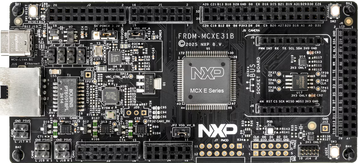
For this example we will be using MCXE31B Freedom board. For getting familiar with the board, visit this link.
Ensure your MCXE31B Freedom board is configured as follows:
J-Link Connection: Connect J-Link debugger to the board
UART Connection: Connect UART cable to the appropriate COM port. In our case, we connected USB to UART converter to pins PTA2 and PTA3
Power: Ensure the board is properly powered via USB
8.1 Program Application to Flash#
APP_ADDRESS = "0x40_0000"

# Erase flash region
%! blhost $BLHOST_CONNECT flash-erase-region $APP_ADDRESS 0x40000

# Write application to flash
%! blhost $BLHOST_CONNECT write-memory $APP_ADDRESS $MBI_OUTPUT
blhost -p COM26 flash-erase-region 0x40_0000 0x40000
Response status = 0 (0x0) Success.
blhost -p COM26 write-memory 0x40_0000 workspace/mcxe31_mbi_smr.bin
Writing memory
Response status = 0 (0x0) Success.
Response word 1 = 19568 (0x4c70)
8.2 Install SMR Entry#
The SMR table allows the host to define up to 8 memory regions and associate each one with an installation
and a verification method.
Install the SMR entry with the authentication tag. The -ef flag enables flash erase functionality so the authentication tag can be written to flash memory.
SMR_AUTH_TAG_ADDRESS = "0x50_0000"
SMR_ENTRY_INDEX = 1

assert os.path.exists(SMR_ENTRY_CONFIG)

# Install SMR entry
%! nxpele $BLHOST_CONNECT -f $FAMILY hse smr-entry-install -i $SMR_ENTRY_INDEX -e $SMR_ENTRY_CONFIG -a $SMR_AUTH_TAG_ADDRESS -t $AUTH_TAG_SMR -ef
nxpele -p COM26 -f mcxe31b hse smr-entry-install -i 1 -e inputs/smr_entry.yaml -a 0x50_0000 -t workspace/auth_tag_smr.bin -ef
SMR entry 1 installation (one_pass) successful
8.3 Install CR Entry#
The Core Reset (CR) table allows the host to associate each CPU-driven subsystem available in a device with up to 8 SMR, so that sanctions are applied on those subsystems after the pre-boot and post-boot phases, depending on the SMR verification status.
CR_ENTRY_INDEX = 0
assert os.path.exists(CR_ENTRY_CONFIG)

# Install CR entry
%! nxpele $BLHOST_CONNECT -f $FAMILY hse cr-entry-install -i $CR_ENTRY_INDEX -e $CR_ENTRY_CONFIG
nxpele -p COM26 -f mcxe31b hse cr-entry-install -i 0 -e inputs/cr_entry.yaml
Core Reset entry 0 installation successful
8.4 Verify SMR#
Manually verify the SMR entry before resetting the device.
# Verify SMR entry
%! nxpele $BLHOST_CONNECT -f $FAMILY hse smr-verify -i $SMR_ENTRY_INDEX
nxpele -p COM26 -f mcxe31b hse smr-verify -i 1
SMR entry 1 verification successful (options: NONE)
8.5 Reset and Boot Application#
Reset the device. The application should boot successfully because the SMR verification will pass.
# Reset device
%! blhost $BLHOST_CONNECT reset

print("\n✅ Positive Test Case: Application should boot successfully!")
print("The red LED should be blinking on the board.")
blhost -p COM26 reset
Response status = 0 (0x0) Success.

✅ Positive Test Case: Application should boot successfully!
The red LED should be blinking on the board.
9. Clean Up (Optional)#
If you want to clean up the SMR and CR entries and restore the device to a clean state:
%! nxpele -f $FAMILY $BLHOST_CONNECT hse cr-entry-erase -i $CR_ENTRY_INDEX --yes
%! nxpele -f $FAMILY $BLHOST_CONNECT hse smr-entry-erase -i $SMR_ENTRY_INDEX --yes
%! blhost $BLHOST_CONNECT flash-erase-region $APP_ADDRESS 0x40000
print("\n✅ Clean up completed")
10. References#
Documentation:#
MCXE31B Reference Manual
HSE Firmware User Manual
SPSDK Documentation: https://spsdk.readthedocs.io/
Command Reference:#
# Get help for HSE commands
nxpele -f mcxe31b hse --help

# Get help for SMR entry commands
nxpimage hse smr-entry --help

# Get help for CR entry commands
nxpimage hse cr-entry --help

# Get help for key-info commands
nxpimage hse key-info --help

# Get help for key-catalog commands
nxpimage hse key-catalog --help